Thank you for partnering with Inventronics by choosing our LED drivers for your next design.
On this page, you will find information required to integrate these drivers into your next system such as:
- Inventronics Driver Family Differentiation
- Driver Features
- Driver Product Pages with Datasheet Links
- Tools Needed for Configuring Driver
- How to Operate the Inventronics Programming Software Interface
- Electrical Design-In
- Thermal Design-In
- Mechanical Design-In
- Warranty Information
Browse the different topics below and reach out to your Inventronics representative for dedicated design-in support.
If you have any questions, please reach out to your technical support representative:
Dimitri De Rop
+31-857-470-061
d.derop@inventronicsglobal.com
EUM Family: Optimized, Compact IP66/IP67 LED Drivers
| Series | EUM-Dx | EUM-Mx | EUM-Lx | EUM-Bx |
| Power Levels | 75W, 100W, 150W, 200W, 240W | 75W, 200W, 240W | 100W, 150W, 200W | 75W, 150W, 240W |
| AOC Method | Wired | Wired | Wireless NFC | Wireless NFC |
| Dimming | Isolated 1-5V, 1-10V, 10V PWM, Multiple Timers | Isolated 0-10V, PWM, Multiple Timers | Isolated 0-10V, PWM, Multiple Timers | DALI-2 D4i, Multiple Timers |
| Dim-to-Off | – | ✓ | ✓ | ✓ |
| Auxiliary Power | – | 12V/250mA | 12V/250mA | 24V/125mA |
| Digital Dimming | – | ✓ | ✓ | ✓ |
| AC Metering | – | – | ✓ | ✓ |
| OTP for LEDs | – | – | ✓ | ✓ |
| End of Life Indicator | – | ✓ | ✓ | ✓ |
| Dimensions (150W) | 178 x 60 x 36.5 mm | 178 x 67.5 x 36.5 mm | 178 x 67.5 x 36.5 mm | 178 x 67.5 x 36.5 mm |
| Warranty | 5 Years | 5 Years | 7 Years | 7 Years |
EBS Second Generation Family (DT2/BT2): Class I/II Drivers:
| Series | EBS-DT2* | EBS-BT2 |
| Power Levels | Releasing 2021 | 40W, 80W |
| AOC Method | Wireless NFC | Wireless NFC |
| Dimming | Isolated 1-10V, Multiple Timers | DALI-2 D4i, AC Dim, Multiple Timers |
| Dim-to-Off | – | ✓ |
| Auxiliary Power | – | 24V, 125mA |
| 16V Bus Power Supply | – | ✓ |
| AC Metering | – | ✓ |
| OTP for LEDs | – | ✓ |
| Output Lumen Compensation | ✓ | ✓ |
| End-of-Life Indicator | ✓ | ✓ |
| Lifetime | 100,000 hrs @ Tc 75° | 100,000 hrs @ Tc 75° |
| Surge Protection | 6kV DM, 10kV CM | 6kV DM, 10kV CM |
| Dimensions | 133 x 77 x 36 mm | 133 x 77 x 36 mm |
| Warranty | 8 Years | 8 Years |
*DT2 models data is preliminary and subject to change
Inventronics offers one of the largest LED driver product offering in the solid-state lighting industry. We are leading global brand with over 10 years’ experience and continue to invest to meet customers needs for today and the future. Our LED drivers line includes constant-power, high current, high-input voltage, constant-voltage, programmable, Controls-Ready and various form factors, as well as many other options to provide design flexibility for virtually every application.
Below are some quick links to our most recent products we feel you will be interested in:
Class I/II DALI-2 D4i LED Drivers
IP66/IP67 DALI-2 D4i LED Drivers
Class I/II Controls-Ready LED Drivers
Cost-Optimized, Compact Controls-Ready LED Drivers
Please check the driver datasheet to verify what type of programmable features the driver supports.
Inventronics free programming software allows users to adjust the light output levels, preset dimming protocols and set the output current based on the system specifications to ensure optimal lighting performance. This software works for wired and wireless programming.
You will need:
- PRG-MUL2 Device Driver (Install First)
- Inventronics Multi-Programmer
Download the User Instructions here.
Note: The interface is only supported on Microsoft systems and the ‘Microsoft.NET Framework 4.0’ version or above is required for operation.
Tools needed for different configurations:
Wired Programming:
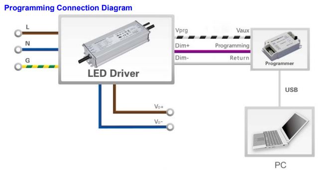
- Inventronics Programming Software
- USB Cable with PC or Laptop
- Inventronics Programmer designed for driver selected
Wireless Programming via NFC:
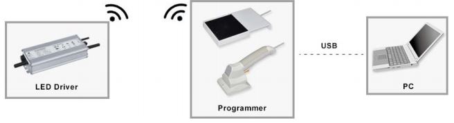
- Inventronics Programming Software
- USB Cable with PC or Laptop
- PRG-NFC-H or PRG-NFC-D or Zhaga Compatible Programming Tool
To learn more about NFC Programming, please read our white paper:
Below we will walk through the steps using the Inventronics programming software interface to configure your drivers. You can also see our extensive library of “How to” videos here: https://www.inventronics-co.com/resources/videos/
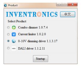
After opening the Inventronics Multi Programmer software, a pop-up window for user account control may appear and ask for permission to allow the program to “make changes to your device”. If this happens, select “Yes” and the below window will open. Select the “0-10V dimming driver” option and then click “Startup”.
The 0-10V Dimming Driver Configuration window will appear after testing if the programmer supports offline programming. (The PRG-MUL2 supports this function.) This window is shown below.
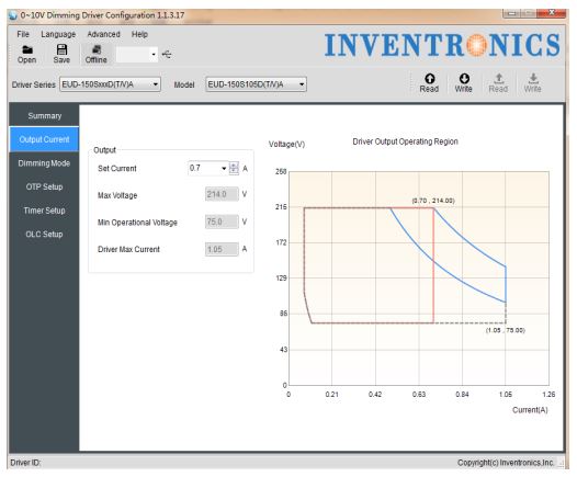
Changing the Output Current and Resulting Optimized Output Voltage Range:
Every programmable driver has a default output current that is specified in the datasheet. This is chosen based upon common output currents used, but can easily be changed through the programming software interface.
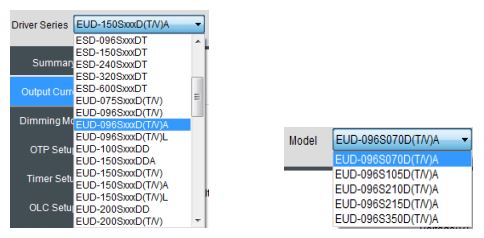
Under Select LED Driver, the drop-down menus for both Series and Model should be selected according to the model being programmed, see the two images below. If the LED driver is connected, the “Read Driver” button may also be selected to autofill these drop-downs.
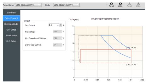
Example 1: Using the EUD-096S210DTA driver, notice the maximum programmable output current for this driver is 2.1A as shown in the image below. (This also happens to be the default output of the driver, but this is not true for every model number. The datasheet should always be referenced for the correct default output current.) The optimized output voltage range for this Ioset is 28Vdc to 46Vdc (60% load to 100% load).
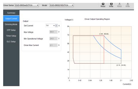
Example 2: The output characteristics were defined as 64Vdc and 1.4A. The EUD-096S210DT Ioset can be programmed to 1.4A, resulting in an optimized output voltage range of 42Vdc to 69Vdc. This is shown in the image below.
Selectable Dimming Methods:
Different series drivers offer different dimming methods. This includes 0~10V, 0~5V, PWM, and timer dimming options as well as the option to enable output lumen compensation.
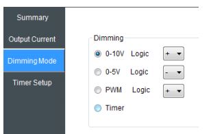
0-10V and 0-5V Dimming:
The default for most drivers is 0-10V Logic as shown in the image below. Some drivers also offer 0-5V Logic which has the same functionality, but reduces the overall dimming signal range.
The wiring diagram and 0-10V dimming curve for the driver may be found in the datasheet as shown in Figure 21. The depicted “dimmer” can be replace with any 0-10V signal and this curve shows that the driver dims down to 10% and then dims-to-off around 0.6V.
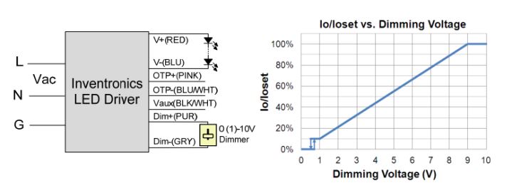
*Note that the dimming performance for every driver, with minimum dimming levels being 10%, 5%, or 1%, will be specified in this curve as well as under the Dimming Specifications section in every datasheet.
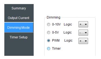
PWM Dimming:
Pulse Width Modulation can also be used to realize dimming with both positive and negative logic as shown in the image below.
Like the 0-10V dimming, the datasheet includes curves to shown the dimming performance given a PWM signal. This is shown below.
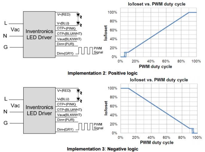
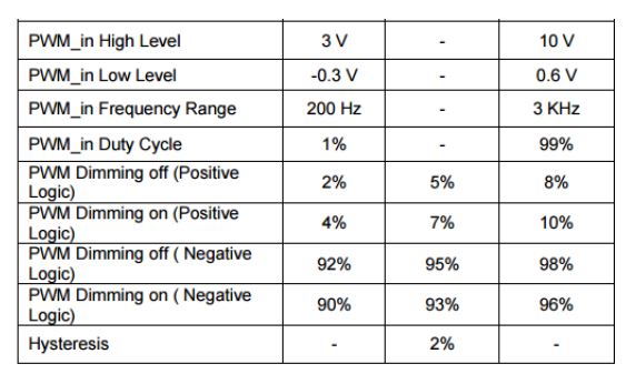
The datasheet’s Dimming Specifications section provides more information related to the PWM signal requirements, as shown below.
Timer Dimming Modes:
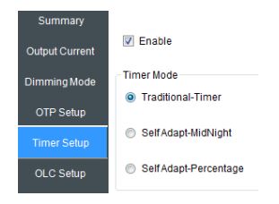
Various applications may need to dim based upon the duration of operation. Some models offer only the Traditional Timer and others offer this in addition to the Self Adapt-Midnight timer as well as the Self Adapt-Percentage timer. By selecting the Timer method as shown in the image below, the Timing Setting tab is highlighted and able to be adjusted.
Traditional Timer:
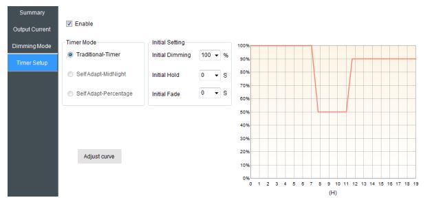
The Traditional-Timer function is the default under the timer dimming modes and allows a curve to be set following the amount of time the driver has been ON. With this, the feature is not a real-time clock, but functions instead as a counter. Referencing the figure below, the “0” on the x-axis corresponds to when the driver has AC power applied and then counts to 19 hours. If the driver is ON for more than 19 hours, the dimming level set at the 19-hour point will continue to be held until the driver is power cycled. The curve can be set to include up to six different dimming stages where the dimming level, hold time, and fade time are all adjustable.
Self-Adapt Midnight:
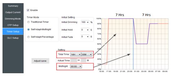
The Self Adapt-MidNight feature is similar to the Traditional-Timer, but it averages the total ON time of the past two days and sets the midpoint, or “MidNight”, of the curve to correlate with half of the average ON time. This may be especially useful for applications where seasonal changes drastically affect the required ON time for the driver.
Referencing the image below, the red curve sets the total possible dimming performance and the purple curve reflects the actual timer performance based upon the averaged ON time. The figure below, shows the actual ON time as 14 hours, with the MidNight set 7 hours after operation.
If the average were to shift to 10 hours ON, there would be 5 hours of operation before and after the MidNight line as shown in the image below. If the average changed to 16 hours, the actual performance would extend and follow the red curve with 8 hours of operation before and after the MidNight setting. When using the Self Adapt-MidNight mode, the curve is either extended or trimmed.
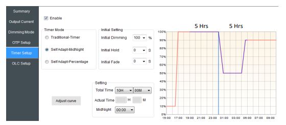
*Note that ON durations will only be calculated as part of the average if the ON time is greater than 5 hours. This helps to avoid faulty averages during abnormal ON events. Also, the average will only be changed if there is a difference less than 15 minutes between two days.
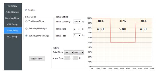
Self-Adapt Percentage:
This is similar to the Self Adapt-MidNight in that the curve adjusts depending on the average ON time calculated by the driver. The difference is that instead of extending or trimming the performance curve, the curve adjusts as a percentage of the total ON time. With this, each specified dimming stage in the curve will be realized, but the total
duration for each dimming stage will vary. The image below shows a curve with an average ON time of 14 hours. The first dimming stage accounts for 30% of the curve with a duration of 4.2H, the second dimming stage accounts for 40% of the curve with a duration of 5.6H, and the last dimming stage accounts for the last 30% of the curve with a duration of 4.2H.
To compare, the image below shows the same curve with an average ON time of 10 hours. The first dimming stage accounts for 30% of the curve with a duration of 3H, the second dimming stage accounts for 40% of the curve with a duration of 4H, and the last dimming stage accounts for the last 30% of the curve with a duration of 3H.
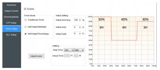
*Note that same as Self Adapt-MidNight, ON durations will only be calculated as part of the average if the ON time is greater than 5 hours. This helps to avoid faulty averages during abnormal ON events. Also, the average will only be changed if there is a difference less than 15 minutes between days.
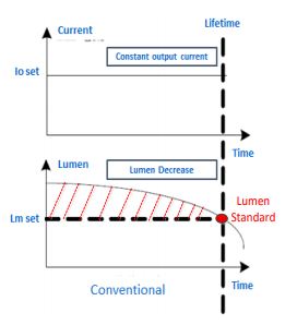
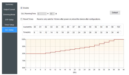
Output Lumen Compensation:
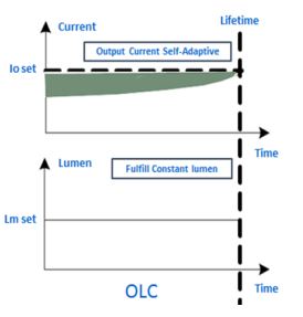
In addition to all dimming methods, Output Lumen Compensation can also be enabled. This feature helps counter anticipated decreases in the luminous efficacy of LED modules to maintain a uniform light output over time. The reduction of light output over time for a traditional design is depicted below.
Using the software interface as shown in the image below, 16 different dimming stages may be set according to expected lumen depreciation. The Ioset percentages and the desired runtime transitions between dimming stages are all configurable by typing values into the field. The total allowable programmed time is 64kH, but is not shown as a default.
Using this feature, constant lumen output over time may be achieved as described in the image below.
Implementing Over Temperature Protection (OTP):
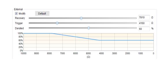
External Over Temperature Protection (OTP) is featured in all newer, full featured series. This built-in feature provides an additional mode of protection for either the LED modules, the LED driver, or any other temperature sensitive component within a luminaire design. A NTC thermistor may be implemented to utilize this protection mode, with
wiring shown in the image below. The LED driver monitors the resistance of the NTC thermistor and if it reaches a predefined trigger value, the output current will de-rate to a predefined percentage of Ioset, allowing the system to cool. As the system cools the output current will gradually increase until it is back to 100% Ioset. It will reach 100% Ioset at the predefined recovery resistance.

The OTP trigger and recovery points are adjustable within the software interface, providing the flexibility to use most any NTC. With this, the points can be set to correspond with any desired temperature as specified within the NTC performance curves. The image below shows each adjustable parameter which can be changed via the slide bar or by typing a resistance value.
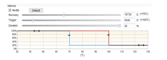
New programming interface adds an adjustable function for internal over temperature protection for some of drivers. The protection triggered temperature, recovery temperature and current derated value can be pre-set in programming interface, please refer to the image below.
Writing to Driver and Saving Configuration Files:
After adjusting the programmable features to best suit a given application, all settings are then defined as a single configuration file. To program the configuration file into the driver, the “Write to Driver” button should be clicked and a window will appear saying that the programming was successful. If wanting to see the last configuration file programmed into a driver, the “Read Driver” button should be clicked and all fields will auto-populate with that configuration file’s settings. If the setting will need to be referenced in the future, the “Write CFG” button may be used to save the configuration as a .ini file for later use. The “Read CFG” button will later be used to open any saved configuration files for programming the driver.
*Note that configuration files can also be saved within the programmer and used without a computer for offline programming. For more information about offline programming, please visit our technical resources page.
LED loads are often customized and the desired lighting effect and requirements vary by application. With this, selecting an appropriate LED driver is more involved than selecting a traditional fluorescent ballast. Several considerations need to be made when selecting the best LED driver for an application.
Defining Output Characteristics:
The primary role of a CC LED driver is to regulate the output current going through the LEDs. With this, the required electrical output characteristics should first be defined. This includes:
• Maximum forward voltage of the assembled LED load (Vf)
• Required output current going through the assembled LED load (Io)
From this, the maximum output power required (Poutmax) and consequently the minimum rated output power of the driver can be defined by multiplying the maximum forward voltage by the output current.
𝑃𝑜𝑢𝑡𝑚𝑎𝑥 = 𝑉𝑓𝑚𝑎𝑥 𝑥 𝐼𝑜
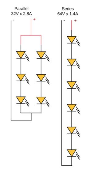
Example 1: assume a load has two LED boards with a maximum forward voltage of 32V optimized for 1400mA. When connecting these boards in parallel, the maximum forward voltage remains at 32V while
the required output current doubles to 2800mA.
32𝑉 𝑥 2.8𝐴 = 89.6𝑊
Example 2: If connecting the same boards in series, the maximum forward voltage doubles to 64V and the required output current remains at 1400mA.
64𝑉 𝑥 1.4𝐴 = 89.6𝑊
Notice in each configuration, the output power is the same, so a driver rated to output at least 90W is required. Also, notice that the required output current and voltage is different. These differences explain why
many different models exist in each series and knowing these parameters will determine which model in a family is best.
Defining Application Requirements to Select the Best LED Driver Family:
After defining the power level, application conditions should be defined:
• Input voltage range
• Luminaire shape
• Ambient operating temperature
• Certifications
• Primary design objective
o Wireless controls ready
o Lowest possible cost
o Longest lifetime
o etc.
With the required output power and application conditions, the best LED driver family may be selected. Continuing with Example 1 and Example 2, if the application requires 120~277Vac input, no specific
shape, -30C to 50C ambient operating temperature, UL certification, and ready for wireless controls, while outputting at least 90W, the EUD-096SxxxDTA family would be best.
This family has 4 different output current models:
• EUD-096S070DTA
• EUD-096S105DTA
• EUD-096S210DTA
• EUD-096S350DTA
The best model for Example 1 requiring 2.8A is EUD096S350DTA. The best model for the Example 2 requiring 1.4A is EUD-096S210DTA.
Note that other driver families of higher rated power output may also be used. For example, if one luminaire design requires at least 90W and another requires at least 130W, it may be advantageous to
select a 150W driver to work for both applications.
Inventronics has a dedicated technical support team ready to answer questions and provide LED driver recommendations based upon provided application information. Please contact your local sales
representative if additional assistance is desired.
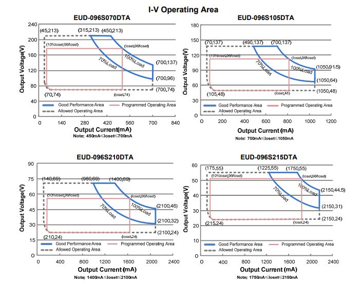
Understanding the I-V Operating Area of Constant Power Drivers:
The programmable line of Inventronics drivers have a constant current output, but also maintain a constant power output for a specified programming range. This means that as the output current is lowered, the output power is not de-rate, but instead the maximum output voltage will rise. This behavior is described in the I-V Operating Area for each model number and the image below provides a zoomed-out view of how this information is presented in datasheets.
Using the EUD-096S350DTA for example, the settable output current range where the driver can still output a full 96W is from 2.45A to 3.5A. The image below highlights this in orange.
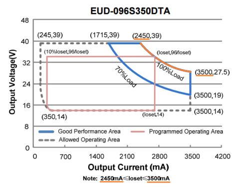
As the output current, or Ioset, is varied, the output voltage upper limit is also varied. The image below shows two examples of this highlighted in orange. If Ioset equals 3.2A, the upper voltage limit is 30V and if Ioset equals 2.6A, the upper voltage limit is 37V.
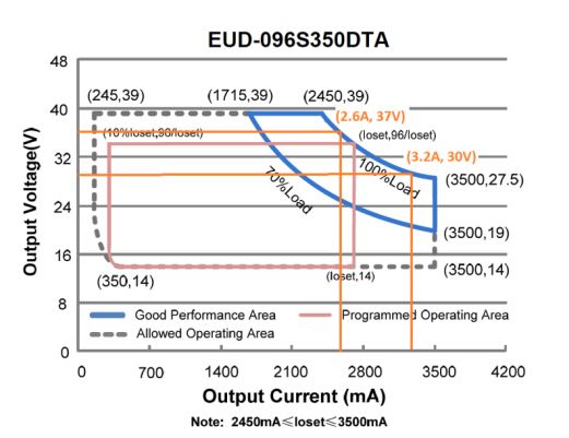
As the output current is lowered to less than 2.45A, the output voltage is limited to 39Vdc and the output power starts to de-rate. The image below shows the limited upper voltage rail highlighted in orange.
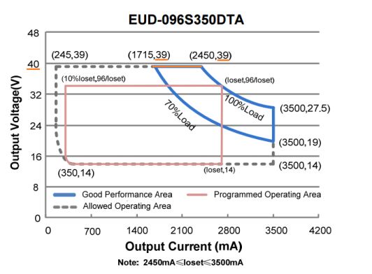
Good Performance Area:
For every programmed, or set, output current (Ioset), there is a minimum and maximum output voltage specified for optimized THD, PF, and efficiency performance. This is defined in the datasheet within
the blue portion called the “Good Performance Area” and is highlighted in orange in the image below. Notice the Ioset and Vout values are provided for each corner of the curve.
The minimum load, or minimum voltage limit, for “good” performance is specified in the curve as 70% of the maximum load. With this information and rearranging the equation for power:
𝑃 = 𝐼 𝑥 𝑉
The minimum and maximum output voltage for any given Ioset can be determined using the following equations:
𝑉𝑓𝑚𝑎𝑥 = 𝑃𝑟𝑎𝑡𝑒𝑑 ÷ 𝐼𝑜𝑠𝑒𝑡
𝑉𝑓𝑚𝑖𝑛 = (𝑃𝑟𝑎𝑡𝑒𝑑 ÷ 𝐼𝑜𝑠𝑒𝑡) 𝑥 %𝑙𝑜𝑎𝑑
For example, when Ioset is 2.45A, the resulting output voltage range is:
96𝑊 ÷ 2.45𝐴 = 39.2𝑉𝑑𝑐
(96𝑊 ÷ 2.45𝐴) 𝑥 70% = 27.4𝑉𝑑𝑐
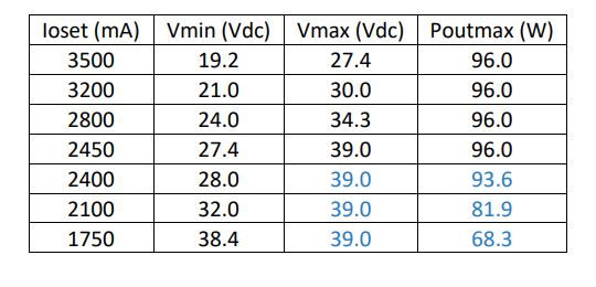
The table below provides the output voltage range specified for good performance. Notice that as Ioset is less than 2.45A, Vmax is limited to 39V and the maximum power output is de-rated to less than 96W.
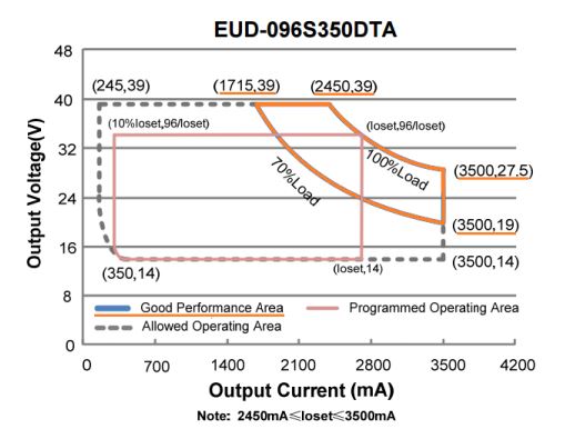
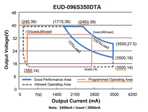
Allowed and Programmed Operating Area:
It is best practice to set the output current and choose a load within the good performance area; however, there may be occurrences where the driver is required to perform outside this area. The image below shows the Allowed Operating Area highlighted in orange. When operating within this area, the Ioset will still be regulated within the allowed tolerance (typically +/- 5%), but THD, PF, and efficiency may be affected. In these scenarios, drivers should be tested with an actual load to determine if the driver performance is acceptable for the application.
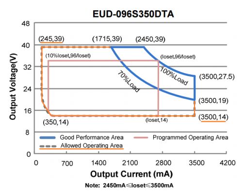
The specified Output Voltage Range found in the datasheet as shown in the table below, specifies the full possible output range depicted in the allowed operation region. Note that this full range is not true
for every Ioset value (as previously shown in the table above).

The Programmed Operating Area describes the maximum voltage and minimum dimming output current for the given Ioset. Notice the minimum dimming output is 10% of Ioset when Ioset is greater
than the minimum Ioset specified for full-power; otherwise, it is fixed to 10% of the minimum Ioset specified for full-power. Still using EUD-096S350DTA as example, this behavior is highlighted in the image below.
For a description of LED driver features, please refer to the driver datasheet.
Installation Instructions:
- LED drivers should be installed by a qualified electrician who is familiar with the installation and operation manual.
- Ensure the installation of the LED driver, either indoor or outdoor, properly complies with the driver’s specifications. Drivers should not be exposed to corrosive gases or liquids.
- Ensure LED drivers are following the installation guideline for enhancing waterproof reliability in outdoor applications and refer to the details in Installation Guidelines-Prevention of Moisture Ingress
- Ensure LED drivers are used with the proper LED, LEP or other specified electrical loads.
Installation Procedures:
- Determine the P (positive) and N (neutral) wires of the main power using a multimeter or other instrument. Verify the impedance and voltage of the ground connection as normal, then disconnect the input power grid.
- Install LED drivers firmly into the lamp bracket with matching screws.
- Connect the positive ‘+’ output of the driver to the DC positive ‘+’ input of the lighting fixture. Connect the negative ‘-‘ output of the driver to the DC negative ‘-‘ input of the luminaire.
- Ensure that all LED driver wire connections are correct after the product is installed and the heat dissipation is properly addressed within in the fixture. Ensure the wiring connections are airtight and waterproof. Only after these requirements are sufficiently met can the driver be operated.
- If any phenomenon occurs such as tripping or irregular operation, disconnect the power main and connection to the luminaire before investigating the problem. If the driver is found to be defective, please replace it or contact the appropriate Inventronics representative for resolution.
Safety:
- Please handle the LED drivers carefully. Do not lift or move the driver using the input or output wires to avoid personal injury and/or product damage.
- A ground connection should be provided to the driver. The drivers’ safety ground connection should be verified.
- Do not disassemble the driver in any way. The length of the input AC wire must exceed 152mm or 6 inches, which is required by Inventronics’ Safety Department.
- Reverse connections, wire crosses and short circuits are strictly prohibited on the input, output and dimming wires. The dimming control wires cannot come into contact with voltages greater than 24VDC or be subject to reverse polarity connections without the risk of damage to the driver.
- Leakage current protection measurement is recommended between the power main and the LED driver. Please limit the number of the drivers used when the end-user operates them with only one leakage circuit-breaker. Sufficient margin needs to be considered when an earth leakage circuit-breaker is chosen. It is recommended that no more than five drivers share one leakage circuit-breaker with a 30mA rating. If the drivers are tripped during operation, please consult a qualified professional to investigate whether there is other possible
leakage. Leakage current measurements should be taken after the cause of failure is confirmed.
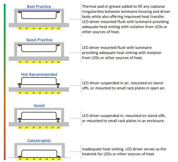
Proper thermal management is critical to luminaire design and impacts driver success in the field. Following traditional lifetime curves, electrolytic capacitors dry out more quickly as heat increases (reducing lifetime), and extreme heat can even lead to solder cracks or component failures. Providing optimal driver thermal performance requires dissipating as little heat as possible (high efficiency) as well as removing heat as effectively as possible (careful layout of components and material selection).
The driver is responsible to distribute heat to its surface, and the luminaire is responsible to pull this heat away from the driver. Heat transfers in three ways – conduction, convection, and radiation. Conduction through a heat sink is the most effective cooling method for drivers, especially for built in designs that utilize an enclosure.
The driver case temperature, or “Tc”, for safety is typically 90ºC and should never be the design target for a luminaire. Instead, the luminaire should manage thermals so that the driver’s worst-case, operational Tc is always maintained within the warranty specification. The luminaire’s ability, or inability, to pull heat away from the driver will ultimately determine the life of the system.
Inventronics is committed to concurrent engineering with our customers to develop the world’s most reliable drivers for the toughest applications.
Under normal circumstances, the driver warranty begins from the date of delivery from Inventronics. If a product has any failure during the warranty period, Inventronics will repair or replace the driver after the failure is confirmed as a true defect.
The warranty is considered out-of-scope when one or more of the following situation occurs:
- The driver suffers damage by not following the instruction manual;
- The driver suffers damage because of improper operation or assembly;
- Improper application or integration with luminaire;
- Disassembly of driver by the end user;
- Severe damage or deformation of the driver’s appearance;
- Damage to the driver’s input or output wires;
- Driver’s identification codes or serial numbers erased, altered or damaged;
- Damage to the driver caused by natural disasters.
Click here to view and download Inventronics full warranty statement.